Schematic Diagram Vs. Actual Circuit
+4
curteneyarellano
jine
denden
Admin
8 posters
 AdminAdmin
- Posts : 18
Join date : 2018-08-01 
 Schematic Diagram Vs. Actual Circuit
Wed Aug 15, 2018 4:23 pm
Electronic schematics represent the most detailed category of electronic drawings. They depict every component in a circuit, the component's technical information (such as its ratings), and how each component is wired into the circuit. It is the most difficult type of drawing or diagram to read, because they require a very high level of knowledge as to how each of the electronic components affects, or is affected by, an electrical current. This chapter reviews only the symbols commonly used in depicting the many components in electronic systems. Once mastered, this knowledge should enable the reader to obtain a functional understanding of most electronic prints and schematics.
Actual Electronic Circuit is composed of individual electronic components, such as resistors, transistors, capacitors, inductors and diodes, connected by conductive wires or traces through which electric current can flow.
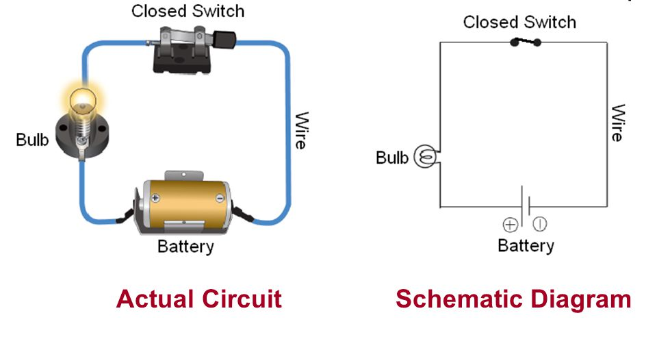
Electric circuits are represented by drawn schematic diagrams like the one on the right. In the other picture, actual components are used to represent each part of the circuit.
Both are essential for us to learn because without prior understanding of schematic diagrams and symbol you will be having a hard time to put into life or do the actual circuit design.
Actual Electronic Circuit is composed of individual electronic components, such as resistors, transistors, capacitors, inductors and diodes, connected by conductive wires or traces through which electric current can flow.
Electric circuits are represented by drawn schematic diagrams like the one on the right. In the other picture, actual components are used to represent each part of the circuit.
Both are essential for us to learn because without prior understanding of schematic diagrams and symbol you will be having a hard time to put into life or do the actual circuit design.
 dendenGuru
- Posts : 10
Join date : 2018-08-19
Re: Schematic Diagram Vs. Actual Circuit
Sun Aug 19, 2018 4:53 pm
schematic diagram is the way to show how a circuit works and it is easy to explain to other people
- dendenGuru
- Posts : 10
Join date : 2018-08-19
Re: Schematic Diagram Vs. Actual Circuit
Sun Aug 19, 2018 4:53 pm
schematic diagram is the way to show how a circuit works and it is easy to explain to other people
- AdminAdmin
- Posts : 18
Join date : 2018-08-01
Re: Schematic Diagram Vs. Actual Circuit
Sun Aug 19, 2018 5:48 pm
That is right but it can be difficult as well to other people who does not have a prior knowledge about symbols. Are you already familiar with the electronic component symbols?denden wrote:schematic diagram is the way to show how a circuit works and it is easy to explain to other people
 jineGuru
- Posts : 11
Join date : 2018-08-20
Re: Schematic Diagram Vs. Actual Circuit
Mon Aug 20, 2018 4:35 pm
What is the difference between wiring diagram and circuit diagram?
- jineGuru
- Posts : 11
Join date : 2018-08-20
Re: Schematic Diagram Vs. Actual Circuit
Mon Aug 20, 2018 4:37 pm
There are three ways to show electrical circuits. They are wiring, schematic, and pictorial diagrams. The two most commonly used are the wiring diagram and the schematic diagram.The pictorial version is not nearly as useful as the schematic, especially if you were trying to obtain enough information to repair a circuit or determine how it operates.
- jineGuru
- Posts : 11
Join date : 2018-08-20
Re: Schematic Diagram Vs. Actual Circuit
Mon Aug 20, 2018 4:38 pm
Admin wrote:That is right but it can be difficult as well to other people who does not have a prior knowledge about symbols. Are you already familiar with the electronic component symbols?denden wrote:schematic diagram is the way to show how a circuit works and it is easy to explain to other people
And also ,Schematic diagrams are used to describe a high level functioning of a system or a process.They simplify and facilitate communication by visualizing the relationships between system objects and making them more obvious.If you are designing or trying to understand a system, diagramming it will certainly help.
 curteneyarellanoGuru
- Posts : 10
Join date : 2018-08-20
Re: Schematic Diagram Vs. Actual Circuit
Wed Aug 22, 2018 2:18 pm
jine wrote:What is the difference between wiring diagram and circuit diagram?
A wiring diagram is a simplified conventional pictorial representation of an electrical circuit. It shows the components of the circuit as simplified shapes, and the power and signal connections between the devices.
A circuit diagram is the use of conventional circuit symbols to provide a schematic diagram of the circuit and its components.
- VersGuru
- Posts : 10
Join date : 2018-08-19
Re: Schematic Diagram Vs. Actual Circuit
Wed Aug 22, 2018 3:10 pm
What is the essence of understanding a schematic diagram?
- VersGuru
- Posts : 10
Join date : 2018-08-19
Re: Schematic Diagram Vs. Actual Circuit
Wed Aug 22, 2018 3:13 pm
which is more difficult to do an actual circuit or its schematic diagram?
- VersGuru
- Posts : 10
Join date : 2018-08-19
Re: Schematic Diagram Vs. Actual Circuit
Wed Aug 22, 2018 3:18 pm
What is the reason behind creating a schematic diagram?
- AdminAdmin
- Posts : 18
Join date : 2018-08-01
Re: Schematic Diagram Vs. Actual Circuit
Wed Aug 22, 2018 3:50 pm
Electronic schematics are the most difficult type of drawing to read or understand because they require a very high level of knowledge as to how each of the electronic components affects, or is affected by, an electrical current but In terms of doing, an actual circuit is harder because you will not know if you can truly make it work.Vers wrote:which is more difficult to do an actual circuit or its schematic diagram?
- AdminAdmin
- Posts : 18
Join date : 2018-08-01
Re: Schematic Diagram Vs. Actual Circuit
Wed Aug 22, 2018 3:54 pm
It is important for us to understand a schematic diagram because it will teach us how the circuit function. It's like you were creating a plan before you make it happen. It can serve as a guide for you.Vers wrote:What is the essence of understanding a schematic diagram?
- margsGuru
- Posts : 10
Join date : 2018-08-22
Re: Schematic Diagram Vs. Actual Circuit
Wed Aug 22, 2018 4:51 pm
What are the different types of circuits?
- margsGuru
- Posts : 10
Join date : 2018-08-22
Re: Schematic Diagram Vs. Actual Circuit
Wed Aug 22, 2018 4:51 pm
What are the four basic components of a circuit?
- margsGuru
- Posts : 10
Join date : 2018-08-22
Re: Schematic Diagram Vs. Actual Circuit
Wed Aug 22, 2018 4:52 pm
How does current flow in a circuit?
- margsGuru
- Posts : 10
Join date : 2018-08-22
Re: Schematic Diagram Vs. Actual Circuit
Wed Aug 22, 2018 4:53 pm
How do circuits work?
 zekmayor09Guru
- Posts : 10
Join date : 2018-08-22
Re: Schematic Diagram Vs. Actual Circuit
Wed Aug 22, 2018 11:28 pm
An electric circuit is in many ways similar to your circulatory system. Your blood vessels, arteries, veins and capillaries are like the wires in a circuit. The blood vessels carry the flow of blood through your body. The wires in a circuit carry the electric current to various parts of an electrical or electronic system.
Your heart is the pump that drives the blood circulation in the body. It provides the force or pressure for blood to circulate. The blood circulating through the body supplies various organs, like your muscles, brain and digestive system. A battery or generator produces voltage -- the force that drives current through the circuit.
Your heart is the pump that drives the blood circulation in the body. It provides the force or pressure for blood to circulate. The blood circulating through the body supplies various organs, like your muscles, brain and digestive system. A battery or generator produces voltage -- the force that drives current through the circuit.
- zekmayor09Guru
- Posts : 10
Join date : 2018-08-22
Re: Schematic Diagram Vs. Actual Circuit
Wed Aug 22, 2018 11:33 pm
Current will flow in a circuit when a wire is connected to battery terminals, electrons flow from negative to positive. Unlike (opposite) charges attract, like (same) charges repel. Electrons have a negative charge—they are repelled from the negative and attracted to the positive
- zekmayor09Guru
- Posts : 10
Join date : 2018-08-22
Re: Schematic Diagram Vs. Actual Circuit
Wed Aug 22, 2018 11:35 pm
Every electric circuit, regardless of where it is or how large or small it is, has four basic parts: an energy source (AC or DC), a conductor (wire), an electrical load (device), and at least one controller (switch).
- zekmayor09Guru
- Posts : 10
Join date : 2018-08-22
Re: Schematic Diagram Vs. Actual Circuit
Wed Aug 22, 2018 11:36 pm
There are two types of circuit we can make, called series and parallel.
- zekmayor09Guru
- Posts : 10
Join date : 2018-08-22
Re: Schematic Diagram Vs. Actual Circuit
Wed Aug 22, 2018 11:48 pm
When creating a schematic, it’s important to make sure you’re illustrating your circuit with the proper level of abstraction. If you’re just trying to convey a high level concept, a napkin schematic might do the trick. If you need to create a schematic for a simulation, then the devil is in the details—you’ll need to be clear about power supplies, signal sources, component values, etc. Or, if you want to create a schematic for a published paper, you’ll need something polished, with the appropriate trade-off between detail and abstraction.
- katieeGuru
- Posts : 10
Join date : 2018-08-23
Re: Schematic Diagram Vs. Actual Circuit
Thu Aug 23, 2018 12:40 pm
In series circuit, the current through each of the components is the same, and the voltage across the circuit is the sum of the voltages across each component. In a parallel circuit, the voltage across each of the components is the same, and the total current is the sum of the currents through each component.zekmayor09 wrote:There are two types of circuit we can make, called series and parallel.
- katieeGuru
- Posts : 10
Join date : 2018-08-23
Re: Schematic Diagram Vs. Actual Circuit
Thu Aug 23, 2018 12:44 pm
The Basic Parts of an Electric Circuit. Every electric circuit, regardless of where it is or how large or small it is, has four basic parts or composition : an energy source (AC or DC), a conductor (wire), an electrical load (device), and at least one controller (switch).margs wrote:What are the four basic components of a circuit?
Permissions in this forum:
You cannot reply to topics in this forum|
|
|